

In this article, we share the details of design of laterally supported steel beam, a step by step guide, methods, formula calculation and other explanation.
So read the article till the end and if you get any valuable information from this than please share it with your friends and colleagues. So Let start,
Table of Contents
What is Laterally Supported Steel Beam?
A beam which is restrained against lateral movement to prevent buckling of it is called a laterally supported beam. In most of the case the buckling of beam is avoided by restraining the compression flange of beam. Making beam laterally restrained allows designers to design a section till its full capacity.
Here are the few examples of laterally supported beam.
- A compression flange of beam embedded into concrete slab. When the compression flange of a beam is fully embedded in a concrete floor, the slab almost certainly furnishes full lateral support. In such a case lateral buckling need not be considered. When the deck of floor-slab merely rests upon the beam, there is the question of whether the potential frictional resistance between the two is capable of developing the force necessary for full lateral support. This must remain largely a matter of judgment as to the reliability of the friction.
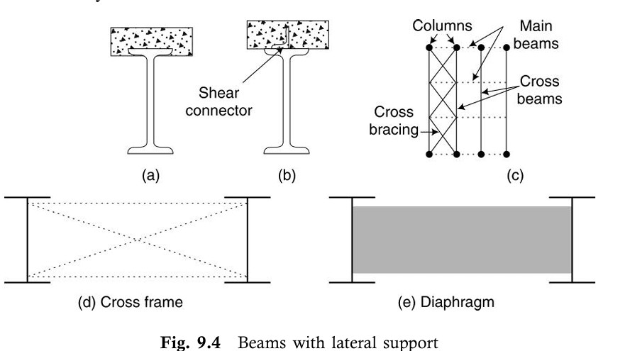
- Shear connectors are welded to the compression flange and are embedded in concrete slab [Fig. 9.4 (b)].
- When the cross beams join the main beams and are connected to the compression flange, full lateral support should be assumed at the connections.
- It may happen that the cross beams are connected to the tension flange of the main beam. In such cases, cross bracing as shown in Fig. 9.4 (c) is done to achieve the lateral restraint.
- The torsional bracing in the form of cross frames or diaphragms as shown in Fig. 9.4 (d, e) prevents twist directly.
Also Read: How to Decide initial Size of Steel Beam?
Design Steps of Laterally Supported Beam
Step 1: Determine the Loads
The first step in designing a laterally supported beam is to determine the service loads acting on the beam. These loads include dead loads, live loads, and any other applicable loads. Once the service loads are known, they are multiplied by a load factor (Yf) to calculate the factored loads. The factored loads are used for the design to ensure safety and reliability.
- Service Loads: Actual loads expected on the beam during its service life.
- Factored Loads: Service loads multiplied by a safety factor (Yf) to account for uncertainties.
Step 2: Calculate Maximum Bending Moment and Shear Force
Using the factored loads, the maximum bending moment and maximum shear force are calculated. These are referred to as the design actions and are critical for selecting the appropriate beam section.
Step 3: Determine the Required Plastic Section Modulus
The plastic section modulus is calculated using the following formula:
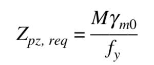
Where:
- M : Design bending moment
- fy : Yield stress of the steel material
- Ym0 : Partial safety factor (typically 1.1 for steel)
The plastic section modulus represents the beam’s ability to resist bending. A trial section with a plastic section modulus equal to or greater than plastic section modulus required is selected.
Step 4: Select a Trial Section
From standard steel section tables (such as ISLB, ISMB, or ISWB), a suitable section is chosen based on the required plastic section modulus.
The properties of the selected section, such as depth (H), flange width (bf), and web thickness (tw), are noted for further calculations.
Step 5: Classify the Section
The selected section is classified as plastic, compact, or semi-compact based on the width-to-thickness ratios of the flange (b/tf) and web (d/tw). This classification determines the section’s behavior under bending and shear.
- Plastic Section: Can develop a full plastic hinge.
- Compact Section: Can reach the yield moment but may not fully develop a plastic hinge.
- Semi-Compact Section: Limited by local buckling before reaching the yield moment.
Also Read: Crack Width Calculation as per IS 3370 – 2021
Step 6: Check for Shear Capacity
The design shear force (V) must be less than the design shear capacity (Vd) of the section. The shear capacity is calculated as:
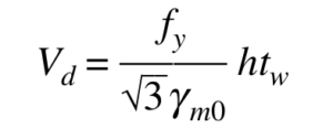
Where:
- H : Overall depth of the section
- tw : Thickness of the web
The beam is then checked for high shear or low shear cases:
- Low Shear: ( V <= 0.6 Vd )
- High Shear: ( V > 0.6 Vd )
Step 7: Check for Bending Strength
For low shear cases, the design bending strength (Md) must be greater than the design bending moment (M). The bending strength is calculated as:
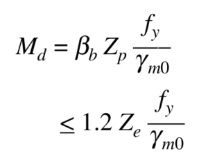
Where:
- Bb : A factor depending on the section classification
- Zp : Plastic section modulus
- Ze : Elastic section modulus
For high shear cases, the bending strength is reduced, and the section must satisfy:
- Mdv >= M (For Plastic or Compact Section)
- Md >= M (Foe Semi Compact Section)
Md = Ze x Fy / Ym0
Mdv =

Where:

- Mfd = Zfd x Fy / Ym0
- Zfd = Zp – Aw x Yw
- Aw = H x tw
- Yw = H/ 4
Step 8: Check for Web Buckling
The web of the beam must be checked for buckling, especially in cases of high shear. The web is considered safe if:

Where:
- d : Depth of the web
- tw : Thickness of the web
If this limit is exceeded, the web must be checked for buckling strength, which should be greater than the design shear force.
Step 9: Check for Web Bearing
The web bearing strength (Fw ) must be greater than the shear force (V). The bearing strength is calculated as:
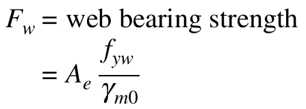
Where:
- Effective Bearing Area (Ae) = (b+2.5(tf+R1)) x tw
- Fyw : Yield stress of the web
Step 10: Check for Deflection
Deflection is a serviceability criterion, and the maximum deflection under service loads should be less than the permissible limit (typically L/300 ), where (L) is the span of the beam.
Reference :
- Limit State Design of Steel Structure by S.K. Duggal
- IS 800:2007
- SP 6