In this article, we explain the crack width calculation for major structural forces like bending moment, direct tension and combined bending and tension for RCC Wall, Slab, Beam, columns, and other structural member. This article also includes the philosophy and basic concept of crack width.
So, read the article till the end, and if you get any valuable information from this article please share it with your friends and colleagues. Also, if you have any query please comment us.
We start the article with understanding of different types of cracks and its type causes to appear in structural member.
Table of Contents
Types of Cracks
Mostly, there are two types of cracks appear in RCC Wall, slabs, beam, etc. That is Structural Cracks and Non Structural Cracks.
Structural Cracks
The cracks which are appear in rcc member due to structural forces like bending moment, shear force, direct tension, torsional moment and shear, etc. are known as structural cracks.

Non-Structural Cracks
The cracks which are appear in rcc member due to quality of characteristic property of material, quality of material, construction, workmanship, etc. are known as structural cracks.

Why Should We Control The Cracks?
Cracks are the major factor for affecting the serviceability and durability of the RCC structure. It becomes a major issue if we not taken care of it during design and construction phases. In long-term point of view, It becomes the major factor for the deterioration of rcc structure and reduce the design life of it.
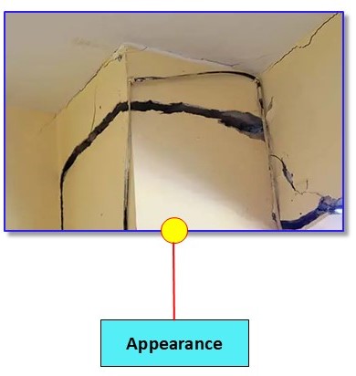
1. Appearance
The appearance of cracks raises questions about the stability of the structure in the minds of users. They often fear potential severe damage if the cracks are not controlled.
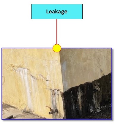
2. Leakage
Here’s the corrected version:
In liquid-retaining structures, cracks are a major concern from a leakage point of view. It not only increase the loss of stored liquid but also lead to dampness and vegetation growth near the structure, which ultimately reduces its durability.
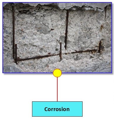
3. Corrosion
Cracks are one of the major factors that lead to the corrosion of reinforcement in RCC structures.
Permissible Crack Width Limit as per IS 3370 – 2021
IS 3370 – 2021 Recommend the crack width limit for liquid retaining structure as per different tightness class. The classification of Tightness Class are listed below.
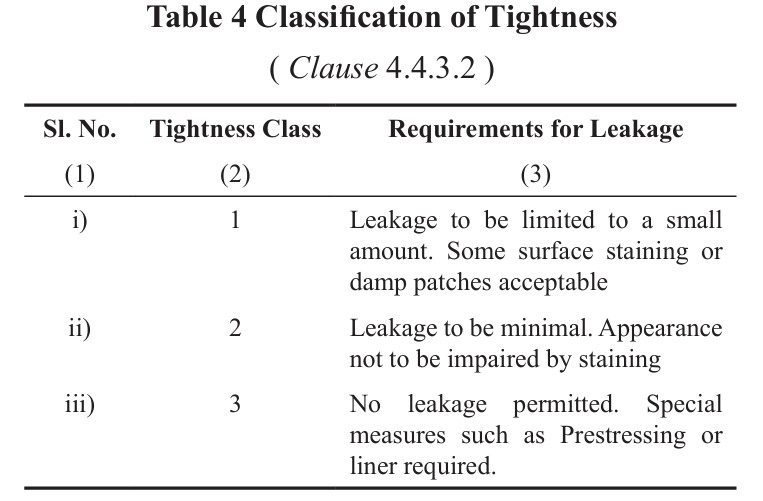
- Tightness Class 1: Leakage to be limited to a small amount. Some surface staining or damp patches acceptable.
- Tightness Class 2: Leakage to be minimal. Appearance not to be impaired by staining
- Tightness Class 3: No leakage permitted. Special measures such as Prestressing or liner required.
Permissible Crack Width Limit as per Tightness Class
- Tightness Class 1: Limiting crack width for cracks expected to pass through the full thickness
of the section ( that is, no compression block) be limited to 0.2 mm. - Tightness Class 2: Limiting crack width shall be 0.2 mm and cracks expected to pass through
the full thickness of the section are avoided unless appropriate measures such as liners or water bars have been incorporated. Alternatively, limiting crack width shall be 0.1 mm. - Tightness Class 3: Limiting crack width shall be 0.1 mm. Cracks should not pass through the full thickness of the section and a compression zone of at least 50 mm should be available. Generally, special measures like application of liners or prestress will be required to ensure this class of water-tightness.
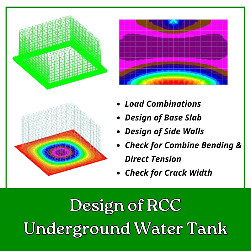
Download Excel Sheets of RCC Underground Water Tank
Steps for Crack Width Calculation
Here is the list of common steps for crack width calculation. These steps are applicable in all type of crack width calculation.
- Determine Neutral Axis (X) & Lever Arm (Z)
- Strain Resisted Due To Stiffening Effect Of Concrete
- Service Strain At Considered Level
- Average Strain
- Design Surface Crack Width
Here we discussed calculation of crack width only for structural cracks.
In any RCC member, structural cracks appear due to majorly 3 forces that is bending moment, shear force and direct tension. so let’s see the calculation of crack width caused by each of these forces one by one.
Crack Width Calculation due to Bending
To calculate the surface crack width due to bending moment, we need to understand the strain and stress diagram of rectangular section.
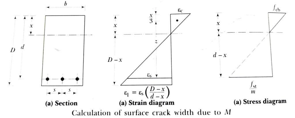
Here are the following steps to calculate the design surface crack width.
Step-1: Calculate the Depth of Neutral Axis
For singly reinforced section, the formula for depth of neutral axis is as shown below.

Where,
- m = Modular Ratio
- db = Dia of Bar
- b = Width of the Section
- Ast = Area of Tension Reinforcement
- d = Effective Depth
In most of the cases, the slabs are doubly reinforced, but if we treat slab as doubly reinforced, the effective concrete cover (d’) may be more than 0.2d and we get x<d’. Therefore it was netter to consider the slab section as singly reinforced.
Step-2: Calculation of Lever arm
For singly reinforced concrete, the formula for calculation of lever arm is as shown as below.

Step-3: Calculate the Strain in Extreme Tension Fiber


Where,
- ε1= Strain at the level considered
- ε2 = Strain resisted due to stiffening effect of concrete bet. Cracks
- εst = Strain due to Service Stress
- D = Overall depth of The Member
- d = Effective Depth
- x = Depth of Neutral Axis
- Ast = Area of Tension Reinf.
- fst = Service Stress
- M = Service Moment
- z = Lever Arm
Step-4: Calculation of Strain due Tension Stiffening of concrete
Concrete is Considered as cracked, it can resist a small amount of tension through uncracked concrete between cracks. This is called Stiffening Effect of Concrete or Tension Stiffening of Concrete.
For a Limiting Design Surface Crack Width of 0.2mm

For a Limiting Design Surface Crack Width of 0.1mm

Where,
- bt = Width of Section at Centroid of Tension Reinf.
- D = Overall depth of The Member
- d = Effective Depth
- x = Depth of Neutral Axis
- a′ = Distance from compression face to the point at which the crack width is being calculated
- As = Area of Tension Reinf.
- Es = Modulus of Elasticity of Reinf.
Step-5: Calculation of Average Strain

Step-6: Calculation of Design Surface Crack Width


Where,
- ω = Design Surface Crack Width
- εm = Average Strain
- acr = Distance From Point considered to the surface of the nearest longitudinal bar
- S = Spacing of Bars
- d’ = Effective Concrete Cover
- db = Dia of Bar
Crack Width Calculation due to Direct Tension
Method to calculate the design surface crack width due to direct tension is shown as below.
Step-1: Calculate the Strain in Extreme Tension Fiber


Where,
- ε1= Strain at the considered level
- ε2 = Strain resisted due to stiffening effect of concrete bet. Cracks
- εst = Strain due to Service Stress
- Ast = Area of Tension Reinf.
- fst = Service Stress
- Es = Modulus of Elasticity of Reinf
Step-2: Calculation of Average Strain

Step-3: Calculation of Design Surface Crack Width


Where,
- ω = Design Surface Crack Width
- εm = Average Strain
- acr = Distance From Point considered to the surface of the nearest longitudinal bar
- S = Spacing of Bars
- d’ = Effective Concrete Cover
- db = Dia of Bar
Crack Width Calculation due to Combine Bending and Direct Tension
When tension is combined with bending, the response of the section depends on the amount of tension and bending or more correctly on the ratio of M/T which is defined as an eccentricity of tension force.
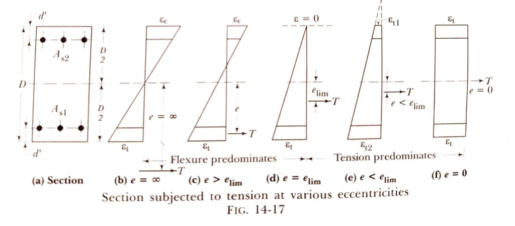
The eccentricity of section e is defined as,


- If e ≤ elim …………………….. Tension Predominates
- If e > elim …………………….. Flexure Predominates
Case-1: Tension Predominates
Method to calculate the design surface crack width in case of tension predominates is shown as below.
Step-1: Calculation of Strain due Tension Stiffening of concrete
For a Limiting Design Surface Crack Width of 0.2mm

For a Limiting Design Surface Crack Width of 0.1mm

Step-2: Calculate the Strain in Extreme Tension Fiber
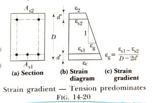


Where,
- ε1= Strain at the level considered
- ε2 = Strain resisted due to stiffening effect of concrete bet. Cracks
- εs1 & εs2 = Strain in Reinforcement
- εg = Strain Gradient
- fs1 & fs1 = Service Stress in Reinforcement
- ρ1 & ρ2 = Percentage of Reinf.
- D = Overall depth of The Member
- d’ = Effective Cover
- M = Service Moment
- Es = Modulus of Elasticity
Step-3: Calculation of Average Strain

Step-3: Calculation of Design Surface Crack Width


Where,
- ω = Design Surface Crack Width
- εm = Average Strain
- acr = Distance From Point considered to the surface of the nearest longitudinal bar
- S = Spacing of Bars
- d’ = Effective Concrete Cover
- db = Dia of Bar
Case-2: Flexure Predominates
Method to calculate the design surface crack width in case of flexure predominates is shown as below.

Step-1: Calculate the Depth of Neutral Axis
To calculate the depth of neutral axis (x), you need to solve the equation as shown below. Use trial and error method to get nearest value of x where the summation of equation is become zero.


Step-2: Calculation of Strain due Tension Stiffening of concrete
For a Limiting Design Surface Crack Width of 0.2mm

For a Limiting Design Surface Crack Width of 0.1mm

Where,
- bt = Width of Section at Centroid of Tension Reinf.
- D = Overall depth of The Member
- d = Effective Depth
- x = Depth of Neutral Axis
- a′ = Distance from compression face to the point at which the crack width is being calculated
- As1 = Area of Tension Reinf.
- Es = Modulus of Elasticity of Reinf.
Step-3: Calculate the Strain in Extreme Tension Fiber


Step-4: Calculation of Average Strain

Step-5: Calculation of Design Surface Crack Width


Where,
- ω = Design Surface Crack Width
- εm = Average Strain
- acr = Distance From Point considered to the surface of the nearest longitudinal bar
- S = Spacing of Bars
- d” = Effective Concrete Cover
- ∅ = Dia of Bar
- Cmin = Clear Cover
References
- IS 3370:Part 2 – 2021 Concrete Structures for Retaining Aqueous Liquids- Code of Practice Part 2 Plain and Reinforced Concrete
- IS 456 : 2000
- Reinforced Concrete Vol – II by Dr. H. J. Shah 8th Edition

